Difference between revisions of "VDL Mode 2"
(Draft) |
(→Initial results) |
||
| (10 intermediate revisions by the same user not shown) | |||
| Line 1: | Line 1: | ||
== Specs == | == Specs == | ||
| − | + | VDL-2 stands for VHF Data Link - Mode 2. It is the 'next-gen' version of [http://en.wikipedia.org/wiki/ACARS ACARS] that is designed to be a higher-throughput communications link supporting a wider variety of messages (e.g. [http://en.wikipedia.org/wiki/Aeronautical_Telecommunications_Network ATN], IP packets). | |
| − | + | ||
| − | + | {| class="wikitable" border="1" | |
| − | + | |+ VDL-2's Magic Numbers | |
| + | |- | ||
| + | ! Property || Value | ||
| + | |- | ||
| + | | Channel allocation || 25kHz | ||
| + | |- | ||
| + | | Modulation || D8PSK | ||
| + | |- | ||
| + | | Symbol rate || 10500 | ||
| + | |- | ||
| + | | Bit rate || 31500 | ||
| + | |- | ||
| + | | Filter || Raised cosine, α = 0.6 (nominal excess bandwidth) | ||
| + | |- | ||
| + | | Constellation || Gray code, 22.5 degree rotation | ||
| + | |- | ||
| + | | Detector lock || 16 symbol synchronisation sequence | ||
| + | |} | ||
== References == | == References == | ||
| − | * | + | * A [http://www.wavecom.ch/PDF/VDL-MODE%202.pdf PDF] summary from Wavecom |
| − | * | + | * A [http://www.eurocontrol.int/vdl4/gallery/content/public/Standards/P1-Chap06.PDF PDF] describing technical aspects of VDL 2, 3 and 4. |
== Demodulation == | == Demodulation == | ||
| + | |||
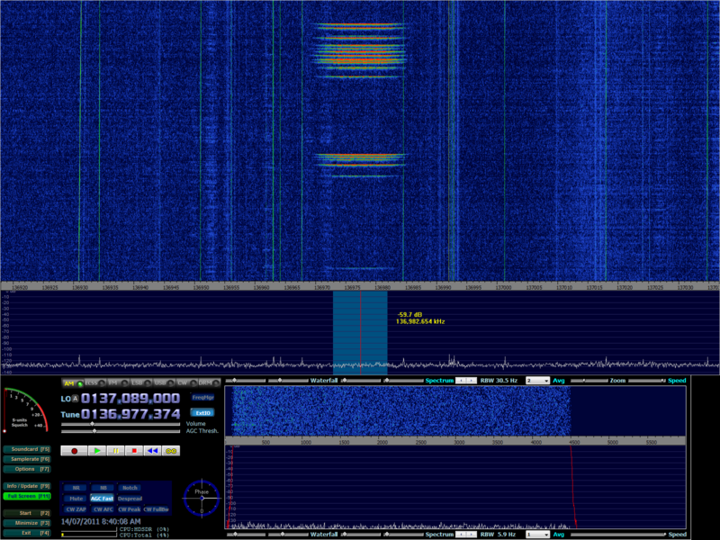
| + | A series of transmissions visible on the waterfall: | ||
| + | |||
| + | [[File:VDL-M2_Waterfall.PNG|800px]] | ||
| + | |||
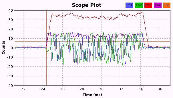
| + | Scope view of a VDL-2 burst: | ||
| + | |||
| + | [[File:VDL-2_Scope.png]] | ||
| + | |||
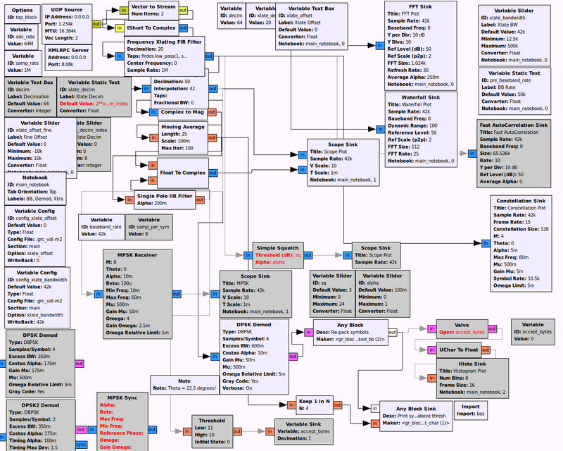
| + | A DPSK demodulator flow graph in GRC that will print out a transmission's initial raw symbols to the console once the received (AM) signal power exceeds a threshold (simple squelch): | ||
[[File:VDL-M2_GRC.png|800px]] | [[File:VDL-M2_GRC.png|800px]] | ||
| + | |||
| + | The flow graph above uses [[GRC Any Blocks]]. | ||
| + | |||
| + | == Initial results == | ||
| + | |||
| + | The beginning of a series of transmissions are recorded (the output is generated by [[gr-baz|''baz.print_char'']]). | ||
| + | |||
| + | You can see the sync sequence appearing soon after the squelch has opened (following three zeros as the transmitter ramps up). There are some bit errors too (optimise demodulator parameters?). The final zero is the 'reserved symbol'. | ||
| + | |||
| + | 00454230<b style="color:red">00002430053004757020</b>717774013045147502324403113674664551207303324143134717422433410225705742... [468 symbols] | ||
| + | 3714211710<b style="color:green">00002630453416757120</b>6305744131250311707376473211422744512073033241635367174224334102661261... [132 symbols] | ||
| + | 36311407111670<b style="color:red">00042634013404757020</b>460760213021510502033116326553022164044614664011402645246340465355... [1763 symbols] | ||
| + | 00413672720023746770<b style="color:red">00042634017404757020</b>0455542030250311507375053210422147 [74 symbols] | ||
| + | 62313547740304040207470<b style="color:red">00042634017004755021</b>021554003065031150735605721042230712237003324063174715422... [132 symbols] | ||
| + | 4266304447134176517604677556375270<b style="color:red">00002630053404757120</b>1455702031651675123245 [76 symbols] | ||
| + | 4106466441600714543221075635650065714071030<b style="color:red">00066264171041575441</b>4055164716 [73 symbols] | ||
| + | 524365770361236070614016300270044222272030<b style="color:red">00042630453406757020</b>53055411302503101254164732114225605526... [131 symbols] | ||
| + | |||
| + | Note: there are three bits per symbols (digits range from 0 to 7). Here the bit order for each symbol is reversed (in case you're wondering why it doesn't match the spec). | ||
| + | |||
| + | {{RF}} | ||
Latest revision as of 10:37, 25 March 2012
Contents
[hide]Specs
VDL-2 stands for VHF Data Link - Mode 2. It is the 'next-gen' version of ACARS that is designed to be a higher-throughput communications link supporting a wider variety of messages (e.g. ATN, IP packets).
| Property | Value |
|---|---|
| Channel allocation | 25kHz |
| Modulation | D8PSK |
| Symbol rate | 10500 |
| Bit rate | 31500 |
| Filter | Raised cosine, α = 0.6 (nominal excess bandwidth) |
| Constellation | Gray code, 22.5 degree rotation |
| Detector lock | 16 symbol synchronisation sequence |
References
Demodulation
A series of transmissions visible on the waterfall:
Scope view of a VDL-2 burst:
A DPSK demodulator flow graph in GRC that will print out a transmission's initial raw symbols to the console once the received (AM) signal power exceeds a threshold (simple squelch):
The flow graph above uses GRC Any Blocks.
Initial results
The beginning of a series of transmissions are recorded (the output is generated by baz.print_char).
You can see the sync sequence appearing soon after the squelch has opened (following three zeros as the transmitter ramps up). There are some bit errors too (optimise demodulator parameters?). The final zero is the 'reserved symbol'.
0045423000002430053004757020717774013045147502324403113674664551207303324143134717422433410225705742... [468 symbols]
3714211710000026304534167571206305744131250311707376473211422744512073033241635367174224334102661261... [132 symbols]
3631140711167000042634013404757020460760213021510502033116326553022164044614664011402645246340465355... [1763 symbols]
00413672720023746770000426340174047570200455542030250311507375053210422147 [74 symbols]
6231354774030404020747000042634017004755021021554003065031150735605721042230712237003324063174715422... [132 symbols]
4266304447134176517604677556375270000026300534047571201455702031651675123245 [76 symbols]
4106466441600714543221075635650065714071030000662641710415754414055164716 [73 symbols]
5243657703612360706140163002700442222720300004263045340675702053055411302503101254164732114225605526... [131 symbols]
Note: there are three bits per symbols (digits range from 0 to 7). Here the bit order for each symbol is reversed (in case you're wondering why it doesn't match the spec).
| ||||||||||||||||||||||||||||||||||||||||||||||||||||||||||||||||


